Radiant at 30: SIG History Part 1 – Goniometry Goes Big
Rick Albrecht is an optical engineer who joined Radiant in 1995. He is the inventor of our Source Imaging Goniometer® (SIG) system.
Ray Tracing for Light Source Characterization
For years optical engineers have traced light rays through optical designs to determine how they will perform. Early on, this ray tracing was done by graphical means on large drawing boards. It’s amazing the quality of optics that could be designed in this very labor-intensive way. This process was greatly improved with the advent of the computer. What used to take weeks or months, now could be done in seconds.
There are two general fields of optical design: imaging and illumination. Optical design for imaging has rules for how light rays can travel from an object to an image and what optics are allowed to do to those rays along the way. Because of these rules it’s possible to trace a few light rays and make very good assumptions about the light rays that aren’t traced. With computers you can trace a few hundred light rays to an image and have a very good idea of the quality of the image provided by a particular optical system.
However, optical design for illumination has fewer and more lenient rules when it comes to evaluating what light rays contribute to illumination distribution. That may sound like an advantage, but that means there are many more paths for light to travel from a source to the target plane than what is allowed in imaging. Instead of tracing a few hundred light rays to get your answer, you have to trace hundreds of thousands, even multiple millions of light rays to determine the illumination distribution.
Far-Field & Near-Field Measurement
In the 90s, even with the speed of computers, it could take many hours to trace enough rays to get an accurate answer. Another important difference between imaging and illumination is that instead of imaging point objects and forming those points in the image plane; an illumination system images many thousands of overlapping images of the light source and adds them up on the target plane.
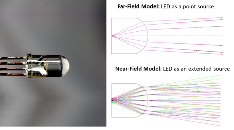
Those calculations can be off (even way off) if you don’t accurately represent what the actual source looks like. Early attempts to describe a light source was to use a goniometer with a single point detector on a long arm and measure the brightness of the source over hundreds of angles. This is defined as “far-field” measurement because the light source was considered a point or nearly so.
However, most illumination systems used reflectors and lenses much closer to the light source, in the “near-field.” The size and shape of the source could be different when viewed from different parts of the optical system. To address this issue, an early approach was to describe a light source by manually drawing an image of the source in something like CAD. This was an improvement, but the accuracy of calculations was still not as good for a complex light source.

Early Radiant Methods
Radiant Imaging [later Radiant Vision Systems] made a significant advancement in characterizing light sources by capturing images of what the source looked like from many angles. This approach takes into account things like differences in illumination across the source, and small structural details, and even things like reflections on the lamp envelope. With a more accurate description of the light source the calculations for illumination optical systems are more accurate.
In the early stages of creating source models, Radiant Imaging setup a light source and camera on an optical table and rotated the light source around a horizontal axis and moved the camera to different positions around the source. This was labor intensive and would only work for lamps that were not sensitive to position relative to gravity.
The First SIG
I joined Radiant Imaging in the summer of 1995. In December of that year, Ron Rykowski [Founder and then-CEO] and I had a long phone call discussing how the process of creating a source model could be automated and how to address some of the shortcomings of the current manual process.
This history of SIG development is written from a mechanical/optical perspective. (There is a parallel software story not covered here.) The goal was to hold the lamp stationary in any operating position and move the camera around the lamp under computer control.
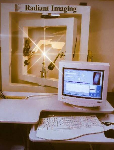
Within a month of that call, Ron wrote into a customer contract the construction of this new type of goniometer that would have the capacity of handling a 7kW arc lamp. Over the next two months I designed the first source imaging goniometer, which was fabricated in a shop in North Carolina, and shipped to Radiant Imaging [then headquartered in Dana Point, CA] by the second week in April 1996. [Former Radiant employee] Joel Deister and I got the goniometer up and running that week so the large arc lamp could be accurately characterized. Here is a photo of that first goniometer:

As you can see in this photo there are two “nested” rings that hold a camera in the inner ring. The lamp under test is held stationary by the outer main frame and is positioned at the intersection of the two rotational axes. The camera can be positioned at all useful angles to capture images of the light source that can be seen by the illumination system to be designed with this information. The whole frame can be rotated into the horizontal position to characterize lamps that will be used in that position.
Adventures with Arc Lamps
One of the source modeling customer projects we had in the late 90s was to characterize almost a dozen high-wattage arc lamps for movie projectors. The wattage ranged from 7kW to 18kW. When you get to the range of 10kW or higher you need to water-cool the lamps. This meant that it was more prudent to ship the goniometer to the customer than to build a facility to operate those lamps at Radiant Imaging.
These arc lamps were under high gas pressure in a quartz envelope. You had to wear protective coverings over your face and chest to handle these lamps even when they were at room temperature. It required about 50,000 volts of DC to start the arc and then you had to run chilled water through the electrodes to keep them from melting. What could go wrong with that?

Example of a high-wattage arc lamp, a 15kW xenon lamp used for an IMAX movie theater. (Photo: By Atlant, CC BY 2.5 )
The customer had a concrete-block room called the Bunker where they tested these lamps because one of the failure modes was an explosion. The goniometer was placed in the Bunker and the computer was in a safe place outside the room.
There was a concern that the radiant heat from such high-wattage lamps would cause the frame of the goniometer to distort and not position the camera properly. For this reason, the goniometer was painted white. Later we found that in some camera positions the white frame in the background would reduce the contrast of the images. Future goniometers would be painted black.
The ability to provide very accurate source models was part of Radiant Imaging’s business model. A large and important customer wanted to purchase a goniometer to make their own source models. This brought about a major decision: Do we sell this technology?
By this time Radiant Source Models™ had become the defacto industry standard that everyone wanted to match. While the concept of taking a bunch of images of a light source to make a source file appeared straightforward, in fact it was a very complex process. Radiant Imaging had refined the process considerably over several years.

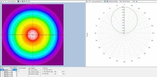
A measurement image (right) shows the radar plot of a light source’s angular luminous intensity distribution (in false-color scale) and a polar diagram (right) highlighting a cross section of that intensity plot.
The SIG Gets Its Name
The decision was made to design and build a new goniometer that would handle the large arc lamps and also small light sources. This required more accuracy in positioning and pointing the camera. The camera was also larger and included a filter wheel to record images in different colors. The new requirements called for a more robust structure. Now that we had two designs for the goniometer, we had to come up with a name to identify them. We settled on Source Imaging Goniometer, or SIG for short. The first white goniometer (that weighed about 250-pounds) was referred to as the SIG-100. The new instrument was called the SIG-200 and weighed in around 1400 pounds.
For the rest of this story, read SIG History Part 2 – Footprints, Frameworks, and Forklifts.
Join Mailing List
Stay up to date on our latest products, blog content, and events.
Join our Mailing List
