Radiant at 30 – SIG History Part 2: Forklifts, Footprints, and Frameworks
Rick Albrecht is an optical engineer who joined Radiant in 1995. He is the inventor of our Source Imaging Goniometer® (SIG) systems. Read Part 1 of the story: Goniometry Goes Big
Heavy Lifting
Our first SIG (the SIG-100) weighed about 250 pounds. The second was called the SIG-200 and weighed 1400 pounds. When machines weigh more than a couple hundred pounds it’s important to plan the logistics of handling and transport. We had to included lifting points and shipping supports in the design of this SIG.
At this time I was living in Chapel Hill, NC and had all the parts made in a shop in Durham, about 14 miles from my house. When the SIG was welded, machined, and painted, I backed my trailer, with shipping crate on top, into the shop and the SIG was loaded with a one-ton overhead crane. Then I drove the SIG back to my house, where I had a shop in the basement.
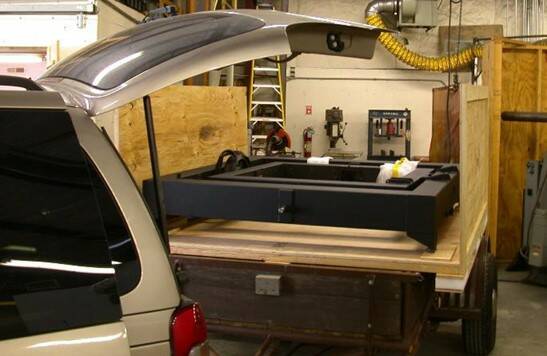
The SIG on its trailer.
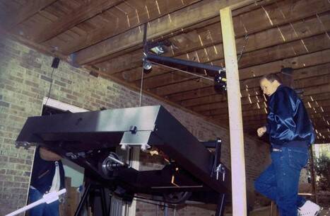
Ron [Rykowski, founder] operating a hand-cranked hoist to lift the SIG out of the trailer and set it on the rolling base.
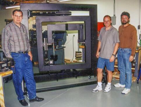
The first SIG-200 before the motors and electronics have been installed. Ron (second from right) and Joel Diester (right) worked on the software while Rick (left) finished assembling the SIG.
After about a month and a half the first SIG-200 was shipped to the customer. A second SIG-200 was then constructed and shipped to Radiant Imaging’s new offices in Duval WA. the help of a fork truck, the SIG-200 was lifted out of the shipping crate and assembled on its rolling stand.
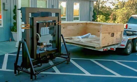
The SIG-200 arriving in Duvall, WA.
The final assembly was done in the Duval office lab. The SIG-200 was much more robust than the SIG-100 and was able to characterize smaller sources with more accuracy.
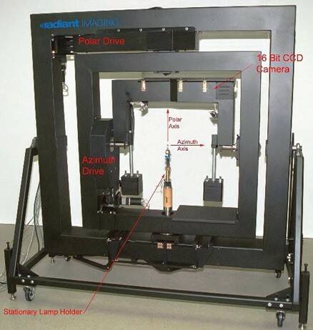
The SIG-200 was able to characterize small light sources more accurately.
This second-generation SIG was rather large and need a large space to operate, particularly in the horizontal position. In addition to the size of the test source, having the requirement to do a horizontal scan called for a large footprint in the scanning lab.
To find a way to reduce the required footprint, I needed to developed a configuration that allowed for a horizontal scan without needing to tip the whole SIG over. To demonstrate this configuration I made a wood model that showed the required motions. This model was used for many demonstrations. This configuration led to the design of the SIG-300.
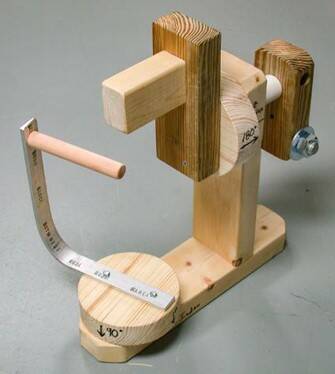
Wooden model of the SIG-300.
The SIG-300 has a maximum field of view about half what was available in the SIG-200, but as you can see in the photo below, it's less than half the size of the SIG-200.
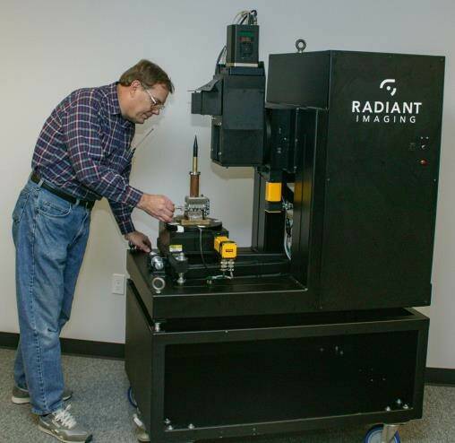
A SIG-300 sitting on a custom wheeled table.
The SIG-300 machine was not intended to scan the large, high wattage arc lamps. While this SIG could do horizontal scans, there was a possible crash situation. This made the software more complex. In early tests, there were some crashes that took out some small precision XYZ stages. In order to prevent serious crashes during testing we made the Horizontal Arm out of Styrofoam, shown in the photo below.
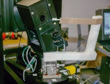
A temporary styrofoam arm used in testing to avoid damaging other parts.
Some interlocks and software safety checks were included. It was decided to use magnets to attach the Horizontal Arm to give an extra layer of safety for the customer. In case the computer got confused and ran into the horizontal arm it would break free without damage. The magnets made it very easy to attach the vertical or horizontal arm.
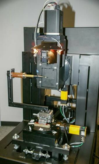
The SIG 300 with the horizontal arm attached. An alignment fixture is mounted on the arm with a white ball on the end.
LEDs Change the Lighting Industry
As LED technology began to expand, there was a market for a SIG with high precision and high magnification. The starting point for designing a SIG begins with defining the maximum and minimum fields of view. The optical path is a fixed length, and the appropriate length needs to be defined.
With some LED chips being 0.25mm, it was important to not only magnify the image, but the motion would need to be several times more accurate than any of the SIGs to that point. The good news was there was no need for a horizontal scan and no mirrors would be needed. The SIG-400 was the next instrument in the SIG family.
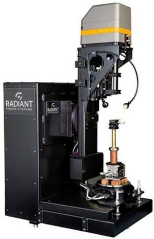
The SIG-400.
With the high magnification of this instrument there was a need to build a very robust lens and camera support. In addition to being robust, it was important to make it easy for the customer to change lenses and get them in focus to within a fraction of a millimeter. The magnification range of this instrument is about 160:1, smallest FOV to the largest FOV. That rang is huge compared to the previous SIGs. This instrument benefited from the many years of building the previous SIGs.
Redesign
Just when I thought all the SIGs we needed had been designed, one more was added to the list. The SIG-200 had been in operation for a decade and there had been many advances in the technology since it began operation. A customer requested a SIG with the capacity of the SIG-200 but needed a smaller footprint.
The approach was to use the same general SIG-300 concept but increase the capacity to the range of the SIG-200. With the increased size we would only need one mirror instead of the two that the SIG-300 used. This simplified the optical system a little. This super sized machine would be called the SIG-310.
Rolling Right Along
One of the many things we learned along the way of building and delivering SIGs was to make sure there was proper logistics for moving and handling these machines that weighed hundreds of pounds. The customer needed to be able to lift the parts out of the shipping crate and the machine needed to pass through standard doorways and negotiate corners in narrow hallways. The customer was given a specification sheet detailing these requirements. That helped the customer be prepared to receive and locate the instrument in the laboratory where it would be used.
In the case of the SIG-310, the shipping crate was equipped with ramps. Once the wheels had been bolted on, with the help of car jack, it could be rolled where needed. Even though there is a lifting eye on top of the SIG, the ramps are an alternate way to get the SIG out of the crate without requiring heavy lifting capacity.
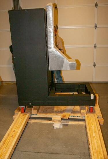
The first SIG-310 ready to roll off the custom pallet that forms the bottom of the shipping crate.
Multiple Configurations
In the photo below, the azimuth arm that carries the camera and optics is in the home position. Rotating that arm 180 degrees provides enough clearance to get through a standard doorway. Notice the outriggers at the bottom of the frame with the white feet. These provide a more stable base and are kinematically attached to the main frame.
In this photo, the SIG-310 is set up for a standard vertical scan with the test light source mounted on the brass rod.
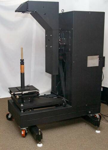
A SIG-310 with the arm in home position, for standard vertical scan.
This next photo shows the SIG setup for an inverted vertical scan. It takes substantial framework to hold the test source in that position and provide clearance for the camera to reach all the required positions.
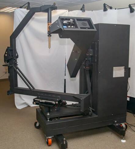
A SIG-310 set up for an inverted vertical scan.
When the upper part of that frame is removed the test light source can be mounted in the horizontal position, as in the photo below.
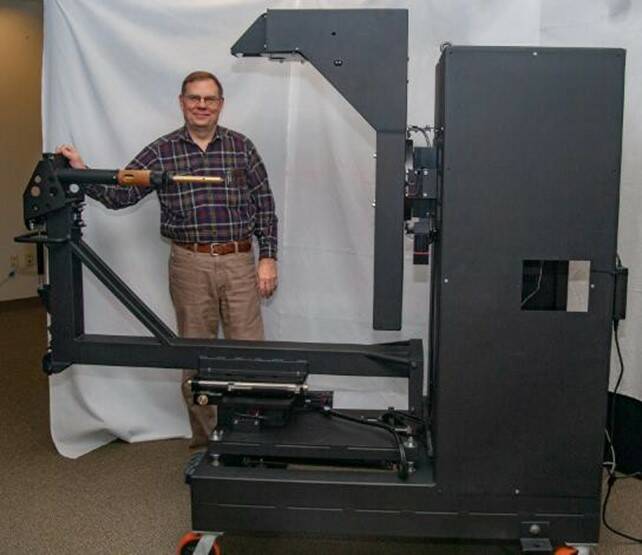
The author, Rick Albrecht, with the SIG-310 he invented.
Bulking Up the Framework
The weight of the framework needed to hold the test lamp at these nonstandard positions required a very robust XY stage attached to the top of the polar rotary stage. There was no easily obtainable commercial stage that had the weight capacity and the precision needed. A custom stage was designed and built for this purpose.
The process of characterizing light sources for use in optical designs has seen a lot of improvements. What stated out as a simple and elegant concept, has become a very complex and sophisticated process that is improving the accuracy of ray trace calculations. The machines discussed in this brief history show some of the evolution in this technology. It has been a joy for this mechanical/optical engineer to work on these machines.
Join Mailing List
Stay up to date on our latest products, blog content, and events.
Join our Mailing List
